Quick answer: Shelf pin sizes usually refer to the post entering the cabinet. A 5 mm pin and a 1/4-inch pin are different: 1/4 inch is exactly 6.35 mm, not 6 mm. Match the original shaft diameter, insertion length, sleeve and support shape. Unload and support the shelf before removing hardware.
Shelf pin sizes: 5 mm vs 1/4 inch
For replacement shelf supports, the advertised size usually describes the shaft that enters the cabinet, not the width of the ledge holding the shelf. Start with an intact pin that is known to fit the same cabinet.
| Size label | Exact or calculated equivalent | Replacement implication |
|---|---|---|
| 5 mm | About 0.197 in | Choose a specified 5 mm support for a matching system. |
| 1/4 in | Exactly 6.35 mm | Larger than 5 mm by 1.35 mm, about 0.053 in. |
| 6 mm | About 0.236 in | A separate diameter; do not treat it as exactly 1/4 in. |
Kreg sells separate 5 mm shelf pins and 1/4-inch shelf pins. Some retail copy rounds the latter to 6 mm. When compatibility is at stake, use the exact nominal product specification and a measured sample instead of that rounded conversion.
These sizes are useful starting points, not an exhaustive catalog. The cabinet’s age, country of origin or appearance cannot establish its hole size. Proprietary plastic pegs and locking supports may require a manufacturer part number even when one dimension looks familiar.
How to measure a shelf pin
Unload the shelf completely and support or remove it before taking out a pin. Keep furniture anchored as its instructions require. For a large or awkward shelf, have a helper support it so removing one fitting cannot drop an edge.
- Choose a sound sample. Use an undamaged original pin from the same support system. Photograph its installed orientation and any retaining clip before removal.
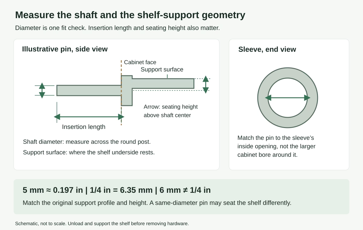
- Measure the shaft diameter. Close caliper jaws gently across the cylindrical post that enters the hole. Avoid the flange, flattened ledge, ribs or decorative cap. Turn the pin and measure again; damage or an irregular shape can make one reading misleading.
- Measure insertion length. Measure from the cabinet-contact shoulder to the tip of the shaft. If the fitting has no clear shoulder or uses a stepped or threaded connection, use its manufacturer drawing rather than guessing an equivalent plain pin.
- Inspect the receiving hole. Look for a sleeve, cracked material, enlargement or debris. If the original sample is missing, a caliper measurement of an accessible clean opening can help identify it, but worn edges are not a reliable specification.
- Record the shelf-contact details. Note the ledge shape, the distance from the shaft center to the surface supporting the shelf, and any notch, screw, cushion or locking tab.
A small ruler may show that two pins differ, but calipers are more useful for distinguishing 5 mm, 6 mm and 6.35 mm. If you still cannot identify the hardware, send the furniture maker clear photos and the cabinet model number. Do not use a powered drill or force a larger peg into the hole as a sizing test.
Check sleeves, support shape and seating height
A sleeve changes what you measure. The pin fits inside the sleeve; the cabinet bore outside that sleeve is larger. Measure a matching old pin or verify the sleeve’s specified inside diameter. Rockler’s 5 mm post listing specifies matching 5 mm holes and offers optional sleeves, illustrating why those are separate parts. Do not remove a sleeve just to fit a different pin.
A long shaft can bottom out. If it reaches the end of a blind hole before the shoulder seats, the support may remain proud of the cabinet side. A shorter shaft is not automatically acceptable either; it may lack the engagement the system requires. Compare the old insertion length with the replacement drawing and the cabinet’s requirements.
A different ledge can change shelf height. Two supports can share a shaft diameter but place their top surfaces at different heights. Mixing them can leave a shelf rocking or resting on fewer supports. Match the profile, projection and shelf-contact height at every support position.
For glass, locking clips, proprietary plastic supports or shelves with underside recesses, use the correct manufacturer hardware. A plain metal ledge may lack the required cushion or retention. A peg that enters the hole has passed only one part of the compatibility check.
What the fit check tells you
| Observation | Meaning / next step |
|---|---|
| 5 mm pin is loose in an opening near 1/4 in | Do not accept the looseness as a fit. Identify the intended pin or sleeve system. |
| 1/4-inch pin will not enter a 5 mm hole | Wrong diameter. Do not hammer it in or enlarge the hole as a replacement shortcut. |
| Diameter matches, shoulder will not seat | Check shaft length, obstruction, sleeve and stepped geometry. |
| Shelf rocks with pins in matching rows | Compare support heights and profiles; inspect the shelf and cabinet condition. |
| Clip will not close or shelf notch misses the peg | Verify shelf thickness, retention design and the exact part number. |
| Hole is cracked, oval or crumbling | Stop using the affected shelf until the damage has an approved repair. A new pin alone is insufficient. |
Replacement shelf pin worksheet
Measure one sound original support, then compare the proposed replacement against every relevant line.
| Feature | Original / replacement |
|---|---|
| Cabinet maker, model and hardware part number | ________________ / ________________ |
| Shaft diameter: mm and inches | ________________ / ________________ |
| Insertion length: shoulder to shaft tip | ________________ / ________________ |
| Sleeve present? Specified inside diameter | ________________ / ________________ |
| Support profile and projection under shelf | ________________ / ________________ |
| Shelf-contact height relative to shaft center | ________________ / ________________ |
| Shelf material, thickness, notch or retaining clip | ________________ / ________________ |
| Required support quantity and documented load limit | ________________ / ________________ |
Photograph the sample beside the caliper reading and keep the part until the replacement is confirmed. If you are refreshing the same cabinet, measure its other hardware separately: cabinet pull hole spacing and replacement drawer slide dimensions use different measurement endpoints.
Final checklist and load limits
- All required supports match the specified diameter, insertion length and profile.
- Each support is fully seated as intended, with no damaged hole or missing sleeve.
- The unloaded shelf sits level on every support, without rocking.
- Any specified cushions, locking clips or shelf retainers are present and engaged.
- The cabinet’s shelf-load limit and anchoring instructions remain applicable.
Pin diameter does not determine shelf capacity. The shelf material and span, cabinet side material, hole condition, support design and load distribution all matter. Do not multiply a per-pin marketing rating by four to promise a safe shelf rating. Use the furniture manufacturer’s limit for the complete assembly.
If that limit is unavailable, do not invent one from the replacement’s diameter or finish. Ask the maker or supplier to confirm the hardware and loading conditions before returning heavy contents to the shelf.