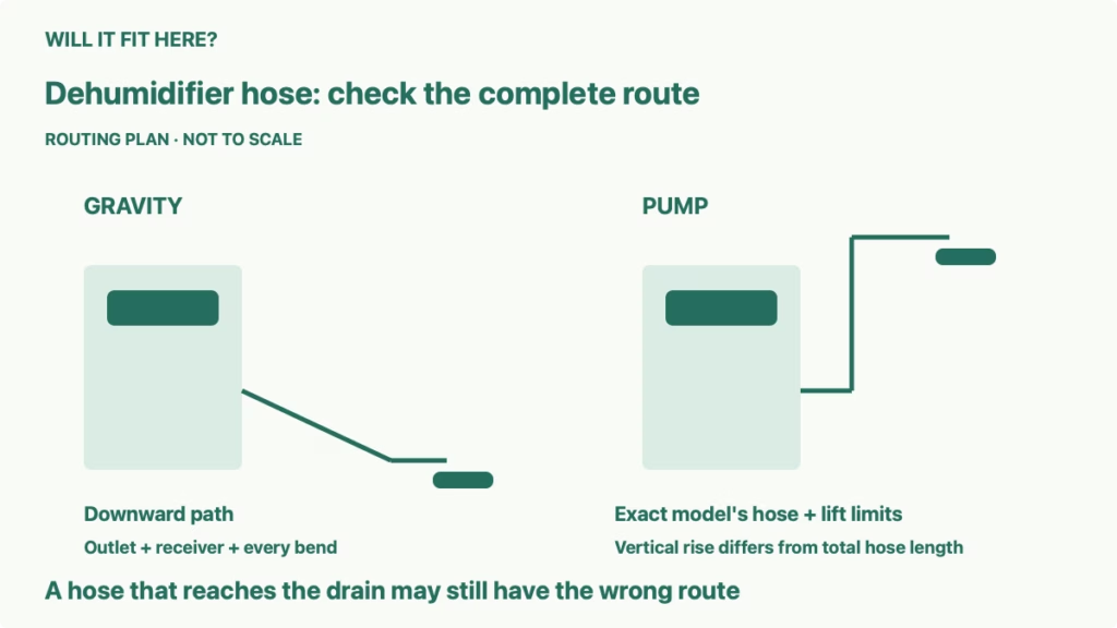
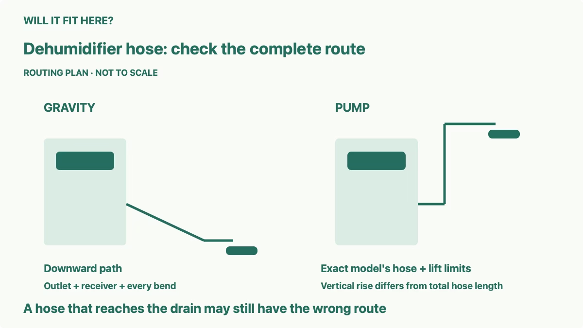
Quick answer: Dehumidifier drain hose fit requires a compatible outlet, an approved hose and a workable route to the receiving drain. Gravity drainage needs a downward path. A pump model uses its own specified hose and lift limits. Enough hose length does not establish that water can reach the drain.
You want to stop carrying a collection bucket, but the closest drain sits across the room or behind a threshold. Compare the actual drain outlet and destination before buying a hose. A hose can reach the opening while its upward loop, submerged end or incompatible connection prevents the intended drainage.
1. Identify the outlet for dehumidifier drain hose fit
Record the complete model number and open its owner’s manual. Confirm whether the appliance supports gravity drainage, a built-in pump, or both. A hose connection alone does not establish that a pump is installed or that the same hose serves both methods.
Locate the connection for your chosen method in that manual. Compare its specified hose type, connector and any supplied adapter with the hose you plan to use. Similar-looking ports can have different functions, so do not select the connection from appearance alone.
GE Appliances’ cited overview distinguishes manual collection, gravity drainage and built-in pump drainage. Its pump-equipped example uses an included pump hose, while its gravity description uses a garden hose. This is a support example to check against a model manual, not permission to connect either hose to any dehumidifier.
Keep the bucket arrangement in the compatibility record. The cited GE overview requires the bucket to remain in place for every method. Check your appliance’s requirements before assuming a drain hose allows the bucket to be removed.
2. Compare outlet height with the entire gravity route
Measure the drain outlet’s elevation and the destination’s receiving point from the same floor reference. Then inspect the route between them. A destination below the outlet can still have an intervening upward section that defeats the intended gravity path.
For a hypothetical outlet 10 inches above the floor and a receiving lip 14 inches above it, a longer hose does not solve the upward path. The example explains a routing conflict; it is not an appliance dimension or an instruction to elevate the machine.
Mark thresholds, door openings and objects that would push the hose uphill. Do not plan a gravity route by drawing only a straight line between the two endpoints. Include every bend and elevation change along the practical path.
The cited GE troubleshooting page calls for downward routing and warns about excess or damaged hose. Use the exact manual’s placement instructions if the proposed route cannot meet that requirement. Avoid improvised stands or other changes that compromise stable appliance placement.
3. Check length, bends and the receiving end
Measure along the proposed hose path rather than across the room. Include the connection approach and the destination approach. Select a permitted length that can follow the route without tension, unnecessary coils or a sharp turn at the appliance.
Look for locations where a door, furniture leg or stored item could pinch the hose. The connector may fit while the first bend immediately collapses the tube. Use the manufacturer’s routing guidance instead of inventing a universal minimum bend radius.
Inspect the receiving end’s position relative to standing water. GE’s troubleshooting guidance says the hose end must remain above standing water in the drain. A hose pushed into water can create a drainage problem even when the appliance outlet and general route appear suitable.
Confirm the destination is an appropriate existing drain for the proposed setup. An opening that physically accepts a hose is not automatically an approved drainage point. If the receiving arrangement is unclear or a new drain is needed, have a qualified professional assess it.
4. Treat pump reach as a model-specific limit
A built-in pump can support a route that differs from gravity drainage, but its maximum lift, supplied tubing and connection rules still apply. Keep vertical rise and total hose length as separate entries on the worksheet.
GE’s cited overview describes an included 16-foot pump drain hose and up to 16 vertical feet of pumping for the setup discussed there. It also says not to extend beyond that supplied hose. Confirm the exact model’s manual before using those figures; they are not specifications for all GE units or other brands.
A proposed route with a short straight-line distance can consume more tubing when it follows walls and rises to the receiver. Conversely, a long horizontal route is not the same quantity as vertical lift. Meeting one limit does not establish that every other route requirement is satisfied.
Check how the selected model activates its pump. The cited GE overview says its pump operates when the bucket is full and may not completely empty it. Residual bucket water alone does not establish a hose-fit failure, and a hose connection alone does not prove pump operation.
5. Reserve appliance, bucket and service access
Plan the machine’s location using its ventilation and placement instructions as well as the hose route. A drain-compatible corner may still obstruct airflow, controls or bucket access. Keep each of these checks separate on the placement plan.
Allow the bucket and any service components to move as the manual requires. A hose tied tightly across the removal path can make ordinary checks awkward. Confirm that the approved route remains workable when the appliance is accessed.
Keep the route out of normal walking and door movement paths. Follow the appliance’s power and wet-location instructions; this guide does not provide wiring changes or electrical installation steps. If a safe location and appropriate existing drain cannot be combined, seek qualified advice before changing the setup.
Observe the initial drainage operation using the manufacturer’s instructions. Check the receiving end and the route rather than assuming that attaching a hose guarantees continuous unattended drainage. Reassess fit if furniture movement, a closing door or another change alters the path.
| Check | Record separately |
|---|---|
| Connection | Exact model, method, port and permitted hose |
| Gravity route | Outlet height, receiving point and intervening elevations |
| Pump route | Model-specific lift and total tubing limits |
| Hose path | Length, bends, pinching and receiving-end position |
| Placement | Airflow, stable support, bucket and service access |
Common questions
Will a longer hose fix a drain above the outlet? Length alone does not create a workable gravity route.
Can I extend the supplied pump tube? Follow the exact model’s limits; the cited GE overview says not to extend its supplied hose.
Can I remove the collection bucket after connecting a hose? Check the manual. The cited GE overview requires it to remain in place.
For another appliance placement problem, see countertop ice maker fit. Browse more Installation & Setup guides for separate connection and operating-space checks.
Official sources and limits
Checked October 7, 2026: GE Appliances’ dehumidifier draining options and drain hose troubleshooting. Use the exact appliance manual for connection, placement and pump specifications. Examples are hypothetical; no firsthand installation, universal hose size or guaranteed drainage performance is claimed.