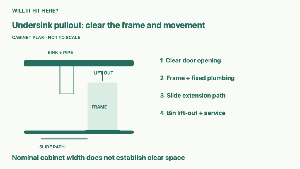
Quick answer: Undersink trash pullout fit requires a clear cabinet opening and an unobstructed three-dimensional path for the complete frame and bins. Compare the exact product’s minimum opening with the narrowest available space after accounting for hinges, plumbing and the sink bowl. A cabinet’s nominal width or a bin’s capacity does not establish whether the sliding assembly fits.
You want a compact waste pullout beneath the sink, but the drain trap and supply lines occupy the space where a normal cabinet accessory would sit. Draw the fixed obstacles first. Then compare the complete closed assembly, its slide travel and the lift-out path used when emptying the bins.
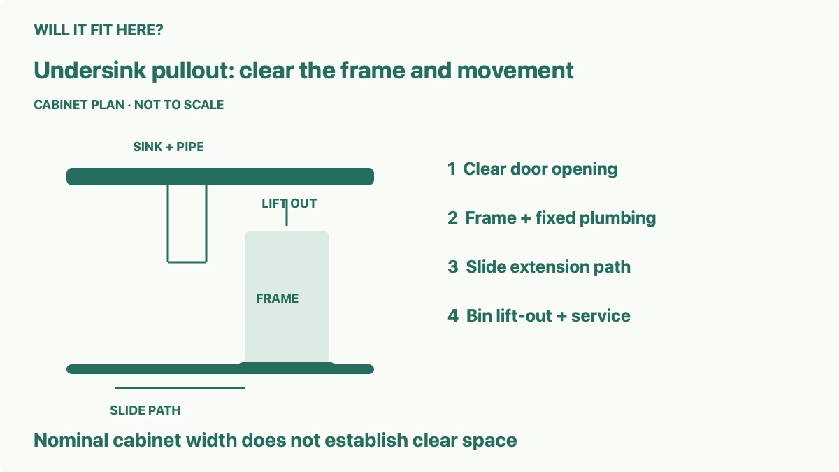
1. Identify the frame for undersink trash pullout fit
Record the complete model number, including the bin and slide configuration. Two products in the same family can have different depths, heights and mounting requirements. The waste bin itself is only one part of the envelope.
The official Rev-A-Shelf page checked for this guide identifies 5SBWC-815S-1 as an undersink pullout with two bins and a soft-close full-extension slide system. Its listed minimum opening is 9.25 inches wide × 18.6 inches deep × 14.5 inches high for both face-frame and frameless cabinets.
Those values apply to that cited model. Use your selected product’s current drawing and instructions for the comparison. A reduced-depth description does not give another model the same minimum opening.
Record whether the arrangement uses a separately purchased door-mount option or opens behind an existing hinged door. The cited product lists optional door-mount brackets separately. Include every planned component in the dimensions and operating path.
2. Measure the actual clear opening
Measure between the obstacles that the frame must pass, not between the outside cabinet walls. A face frame, central stile, hinge or door stop can reduce the useful width. Keep the cabinet type beside the measurements so that you use the corresponding manufacturer’s requirements.
Measure usable depth from the instructed front reference to the rear obstruction. Include the space occupied by plumbing and fittings wherever they intersect the frame’s height. The cabinet’s overall depth may be larger than the uninterrupted depth available for the product.
Measure height from the intended mounting surface to the lowest obstruction over the whole footprint. The sink bowl can sit lower than nearby countertop space. A height reading at one clear corner does not approve the space directly below the bowl.
As a hypothetical example, a 10-inch door opening reduced to 9 inches by a hinge would not meet a 9.25-inch minimum. Record the actual obstruction instead of calling the cabinet “10 inches clear.” The example illustrates a comparison; it is not a measured cabinet.
3. Map plumbing in three dimensions
Draw the drain trap, waste pipe, supply lines, shutoffs and any disposal unit from more than one view. Record their width, depth and height relative to the mounting surface and the product’s front reference. A top view alone can hide an obstruction that hangs over a bin.
Mark the product’s complete closed envelope on a paper or cardboard mockup using confirmed dimensions. Keep it clear of the plumbing without touching, bending or moving a pipe. Compare the frame, bin lids and slide components, not merely the empty area around the floor.
The manufacturer’s product page asks users to account for obstructions such as plumbing and hinges. This is why a minimum-opening pass is the beginning of the under-sink assessment rather than a guarantee of fit in every sink base.
Do not treat an angled supply hose as space that can be casually pushed aside. If a fixed obstruction prevents the intended arrangement, select a different accessory or have a qualified professional assess any plumbing change. This guide does not provide pipe rerouting.
4. Check slide travel and door movement
Draw the complete extended assembly. Include any bin handle or lid that changes the outside profile when the product moves. A closed frame can clear the drain trap while its raised handle or lid encounters an obstacle during use.
Open the existing cabinet door to the position needed by the product. Check the hinge projection and the path of the moving frame past the door edge. A product that enters the cabinet once during assembly may still strike a door during every pullout.
Reserve front space for the extension and the person using it. Compare the planned travel with nearby cabinet doors, an opposing appliance or a narrow kitchen aisle. Keep the manufacturer’s extension dimension separate from the closed cabinet depth.
If the exact extended projection is not published, obtain it before purchase. Do not assume “full extension” describes the same distance for every slide or that the product drawing includes the user’s access space.
5. Reserve bin removal and service access
Check how the bin is removed from the frame for emptying. A lift-out bin needs space above and a route out, which can differ from the sliding path. Use the handle in its normal position and include the lid where relevant.
Consider a normally filled bin rather than only an empty flexible container. The fit plan should allow normal removal without forcing the bin around the sink bowl or pressing it against plumbing. Do not rely on bending the container into a shape absent from the manufacturer’s instructions.
Keep access to existing shutoff valves and other service points. Verify that the assembly can be removed or positioned as instructed for maintenance. A frame that hides a valve permanently can make a seemingly compact arrangement impractical.
Follow the model’s mounting and load requirements. Before any fastening, use the manufacturer’s instructions and confirm a suitable mounting surface; hidden plumbing or other services need proper assessment. Choose another location or product when the required space remains uncertain.
| Region | Independent fit result |
|---|---|
| Door opening | Narrowest width after hinges and frame |
| Closed assembly | Complete width, depth and height |
| Plumbing | Fixed obstacles clear of the product envelope |
| Extension | Frame, door and front-access paths |
| Removal | Bin lift-out and service access |
Common questions
Does a 24-inch sink base guarantee fit? Measure the actual clear opening and fixed obstacles for the selected frame.
Can bin capacity tell me the frame’s width? Use the complete product drawing and minimum opening.
Does closed fit settle the decision? Check extension, lid or handle movement and bin removal too.
For another operating-space comparison, see countertop ice maker fit. Browse the Installation & Setup guides for separate compatibility checks.
Official source and limits
Checked October 7, 2026: Rev-A-Shelf 5SBWC-815S-1 undersink pullout. Confirm the selected model’s current dimensions and instructions. Examples are hypothetical; no firsthand installation or plumbing clearance is claimed.