Quick answer
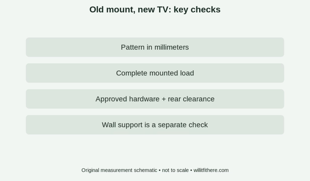
An existing mount is a reuse candidate only when the exact mount supports the new TV’s hole pattern, mounted load and stated size requirements, and the approved hardware fits its rear housing. A matching diagonal or matching VESA number alone is insufficient. The wall attachment needs a separate qualified assessment.
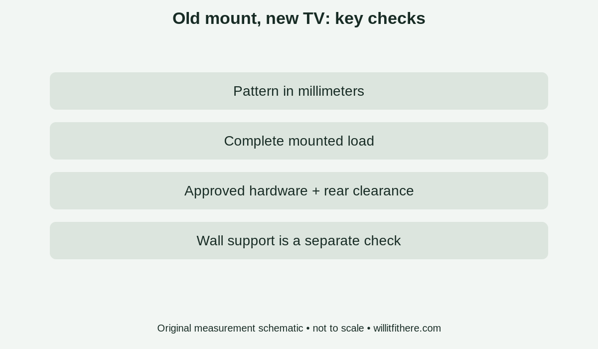
1. Identify both products before comparing them
Find the mount’s maker, model and revision on its label, purchase record or original manual. “Universal TV bracket” is not a usable model identifier. Photograph the wall plate and television-side components without dismantling a supported television. If access is difficult, have the person handling the replacement identify them during the work.
Record the new television’s complete model number and obtain its mounting information. Do not use a comparison table for a neighboring screen size. For the existing mount, use its own instructions and the manufacturer’s compatibility tool where available. SANUS provides a MountFinder tool for its products.
If the mount cannot be identified, the load rating or original components remain uncertain. Treat that as an unresolved compatibility check rather than estimating strength from the thickness of the metal.
2. Match the hole pattern in millimeters
VESA-style spacing is recorded horizontally × vertically between mounting-hole centers. A 400 × 300 pattern is 400 millimeters across and 300 millimeters high. It is different from 300 × 400 and from 400 × 400. Measure the hole centers, not the outside edges of the rear housing or the diagonal between holes.
For a purely dimensional example, 400 millimeters ÷ 25.4 = approximately 15.75 inches. Likewise, 300 millimeters is approximately 11.81 inches. Use the native millimeter specification to compare patterns; converting and rounding through inches can obscure a close mismatch.
| TV pattern | Mount documentation | Screening result |
|---|---|---|
| 400 × 400 mm | Explicitly supports 400 × 400 | Pattern matches only |
| 400 × 400 mm | Supports up to 400 × 300 | Pattern does not match |
| 300 × 200 mm | No readable model or manual | Unverified |
“Up to” is meaningful only in the context of the mount’s supported patterns and configuration. Do not assume every intermediate rectangle is approved.
3. Compare the complete mounted load
Use the television’s weight without its table stand when that stand is removed for mounting. Include attached accessories according to the mount manufacturer’s load definition. A soundbar or accessory bracket hanging from the TV-side assembly can add load even though it did not come in the television box.
In a hypothetical case, a 52-pound television plus 8 pounds of mounted accessories totals 60 pounds. An identified mount with a 55-pound limit fails that load check. A 70-pound rating would pass the numerical load comparison, but would not resolve pattern, hardware, size or wall-support requirements.
Do not use a manufacturer’s safety-test multiple to exceed the published working limit. Equally, do not assume that a lighter replacement television is approved merely because the older one was heavier. Its dimensions, mounting-hole location and permitted bracket arrangement can differ.
4. Check screws, spacers and rear contact
A hole-pattern match says nothing by itself about screw diameter, thread, engagement depth or approved spacers. Those details must come from the TV and mount instructions. Old television screws are not automatically correct for the replacement. Avoid assembling an improvised assortment just because it seems to thread in.
The rear housing may have recessed holes, a curved section or an equipment bulge that changes how the rails contact it. Confirm that the approved arrangement leaves the brackets seated as intended and does not obstruct vents or connections. A mount that spans the holes can still interfere with a connector.
Do not drill extra holes, cut the bracket, stack unapproved spacers or add a generic adapter to turn a failed match into an apparent pass. Ask the mount manufacturer about an approved solution for the exact pair. This is a compatibility review; actual assembly belongs to the documented procedure and an appropriately competent installer.
5. Check screen position and movement space
The mounting holes are not always centered vertically on the display. Reusing the same wall plate can therefore place a new screen higher or lower than the old one. Compare the distance from the mounting-hole reference to the bottom and top of each television before assuming the visible result will remain unchanged.
For an illustrative measurement, if the new screen extends 4 inches farther below the same mounting reference, a former 3-inch gap above a soundbar becomes a 1-inch overlap. Matching pattern and load would not prevent that collision. Have the final position checked before the television is hung.
For a moving mount, evaluate the intended viewing positions as well as the flat position. A larger screen may contact a wall, cabinet or nearby object sooner. Cable reach and access may also change. Use the manufacturer’s documented range; do not force movement past a stop.
6. Keep hardware compatibility separate from wall support
An old installation holding the previous television is not proof that every connection remains suitable for the replacement. Unknown wall construction, missing hardware, corrosion, deformation or loose components require assessment. A visual glance cannot certify concealed wall attachment.
This article does not provide drilling, anchor selection, structural-load calculations or electrical-routing instructions. Have wall suitability and the existing attachment checked by a qualified installer where needed. If the mount was supplied with a particular furniture system or enclosure, that system may add requirements beyond the mount label.
Document the outcome as two separate statements: the TV-to-mount pair is compatible, and the mounting location and attachment are approved for that use. Neither statement should be inferred from the other.
7. Complete the reuse decision sheet
- Exact TV model and mount model/revision identified.
- Supported horizontal × vertical hole pattern matches.
- Complete mounted load stays within the documented rating.
- Published TV-size requirements are satisfied.
- Correct hardware and rear-housing arrangement confirmed.
- Ports, vents, screen position and intended movement stay clear.
- Mount condition and wall attachment assessed separately.
If a seller only asks for the screen size, provide the complete model numbers anyway. Send photographs of the labels and the relevant manual pages when seeking manufacturer confirmation. Save the response with the manuals so the next replacement does not start from another guess.
Mark a missing answer as “unverified.” That is more useful than a provisional yes because it identifies the exact question still preventing reuse.
8. Source ledger and scope
The SANUS mount-size chart illustrates why mounting pattern, screen range and load capacity are separate specifications. It is a historical catalog-style reference, not a current approval for an unidentified bracket. For an actual decision, the exact mount’s current or archived manufacturer manual governs its limits.
The SANUS tools page was checked October 5, 2026. All numerical examples in this guide are explicitly hypothetical or unit conversions. None declares a specific existing wall installation safe. If identification or documentation cannot be recovered, ask the manufacturer or installer to resolve the uncertainty before reusing the mount.